PROJECT
Make a fully adjustable tablet stand

Gord Graff

Find more Featured projects , Gifts / Crafts projects
Finally, a tablet stand that isn’t a pain in the neck.
Despite the popularity of tablet computers, especially as a way to stay connected with family and friends during Coronavirus restrictions, tablets have one thing in common: using them can be a real pain in the neck…literally. Using a tablet when it’s resting on a table at a slight angle or on a countertop creates uncomfortable neck strain. Even the available folding tablet stands and cases fail to raise the tablet high enough for prolonged, comfortable use while you’re sitting or standing.
The solution is simple: raise and tilt the tablet to a comfortable viewing height. Because of its adjustable height and adjustable viewing angle, this tablet stand makes it much more comfortable to use a tablet for prolonged periods of time. Whether you’re sitting at a desk or table, or standing at a kitchen counter or a workshop workbench, your tablet viewing from now on will no longer be a pain in the neck.
Make a fully adjustable tablet stand
The building process
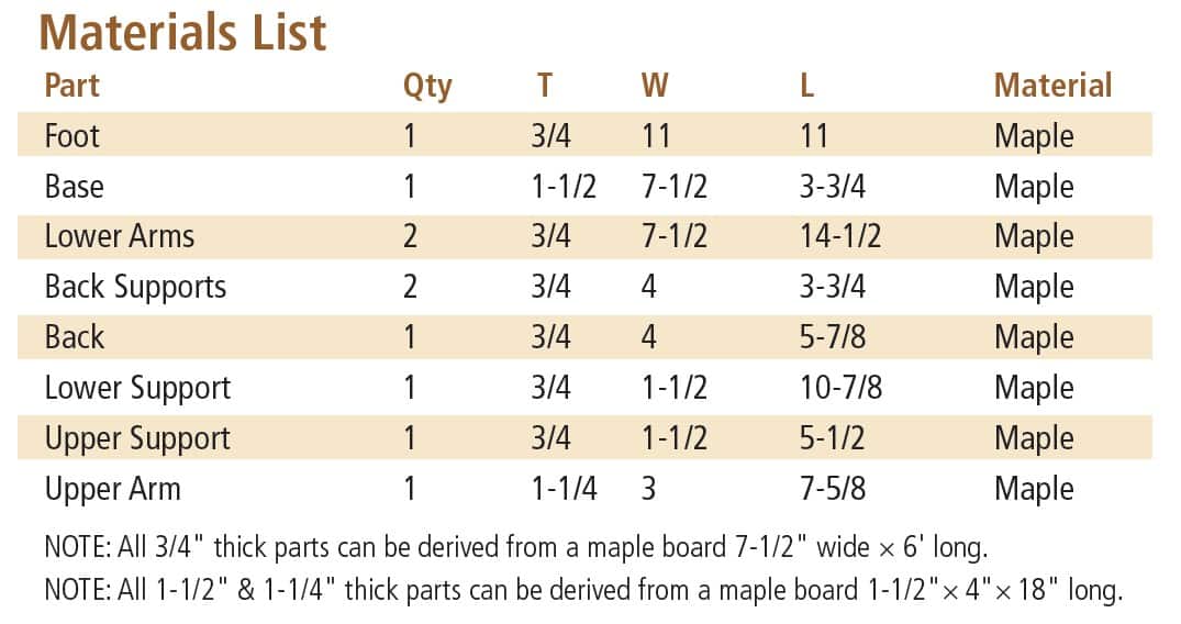
I chose hard maple for this project, but the design lends itself to any species you may choose. All of the 3/4″ thick parts can be easily obtained from a single board 7-1/2″ wide × 6′ long. The 1-1/2″ and 1-1/4″ parts can be acquired from a piece of stock 1-1/2″x 4″ × 18″ long. Both of these measurements leave plenty of room to avoid a few defects.
With the material jointed and planed to the required thicknesses, it’s time to cut the stock needed for the 11″ diameter circular foot glue-up.
First, the foot
Consider using boards with a pleasing grain pattern for the foot for maximum visual effect. After all, this panel will end up being the largest piece of the project so you’d like it to be visually appealing. I’ve glued up this panel oversized at 12″ × 15″.
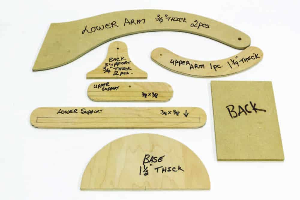
Optional templates
Except for the 11″ diameter foot, I’ve taken the time to make templates out of 1/4″ plywood or MDF for each of the parts of this tablet stand. This part of the project is optional but working from templates makes building several tablet stands easy and I expect to make several more. It’s also an easy way to determine the best use of a board.
Before starting, measure your tablet and make the appropriate dimensional changes to suit your tablet’s size. When using the part templates, it’s fast and easy to trace out the parts required on your material.
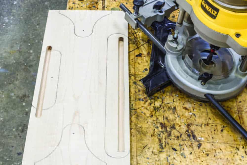
The upper and lower supports are traced out along the edges of the material to accommodate the router’s fence used to rout a 3/8″ wide × 3/8″ deep groove using a 3/8″ up-cut spiral bit.
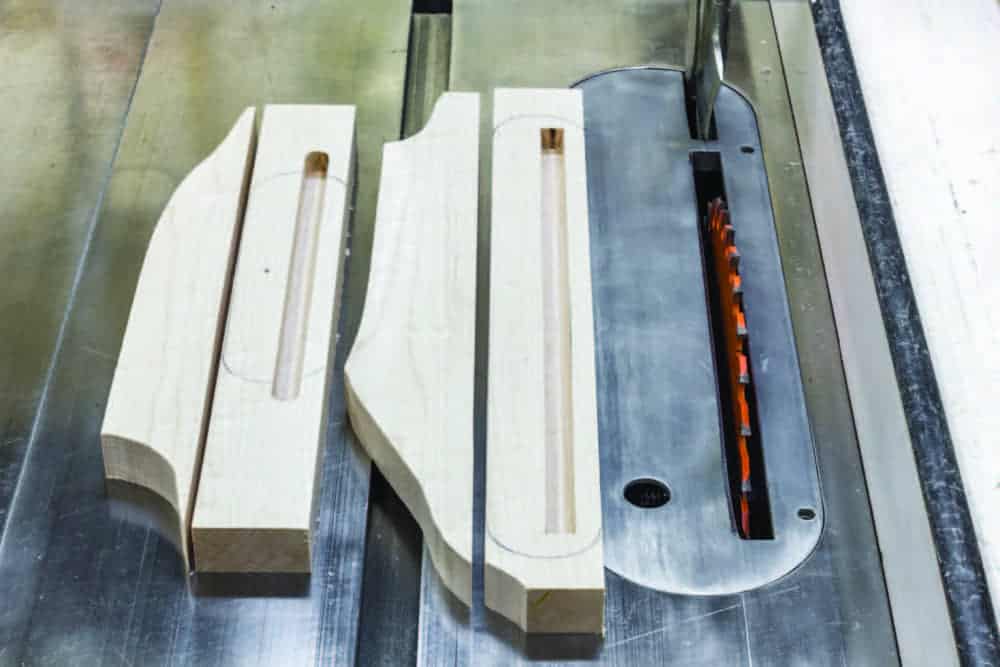
With the groove routed in the upper and lower supports, and the other parts cut out on the bandsaw, you can now cut out the upper and lower supports to 1-1/2″ wide using your table saw.
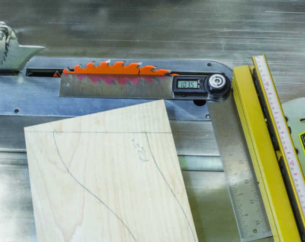
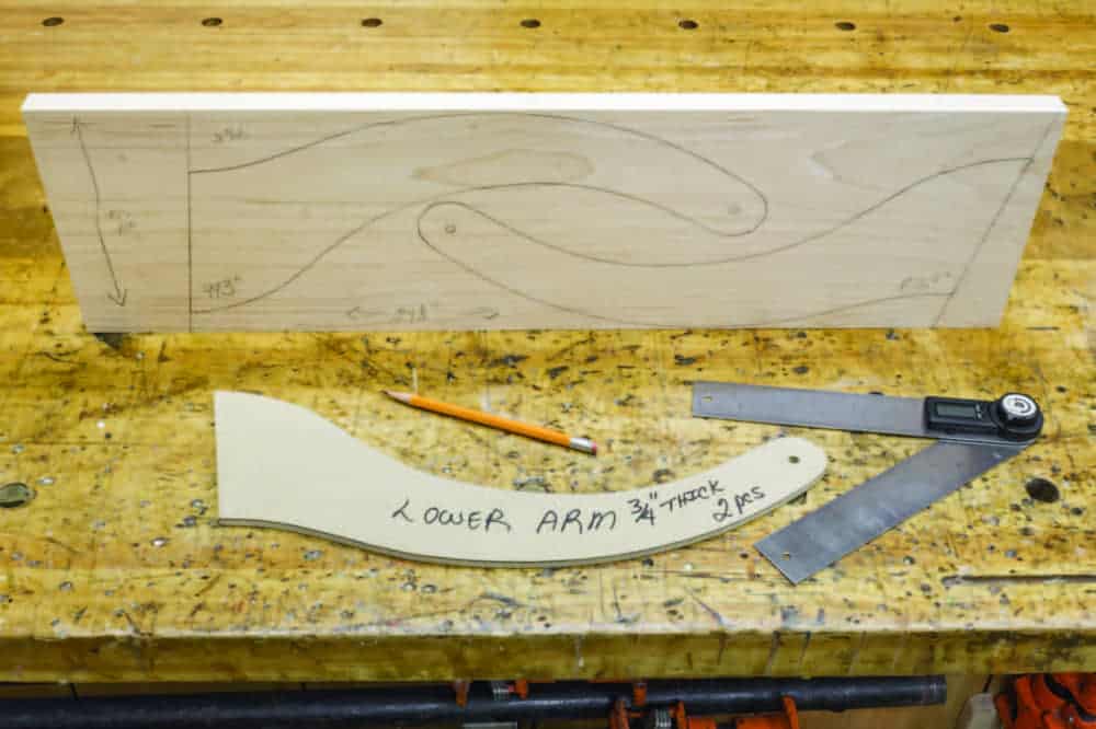
If you were to place the lower arm’s template flush to the bottom of a board, the size of the board required would be 7-1/2″ × 14-1/2″, but you can use narrower boards. Here, I’ve used a 6-3/4″ wide board and traced the lower arms on the material at an angle to gain the use of this narrower board and to take advantage of the grain pattern. The result is the lower arm’s bottom edges are not perpendicular to the edge of the board, but that’s not a problem.
Using a digital angle finder, you can easily measure the angle of the base of the lower arm and transfer that angle to the table saw’s mitre gauge and cut that exact angle.
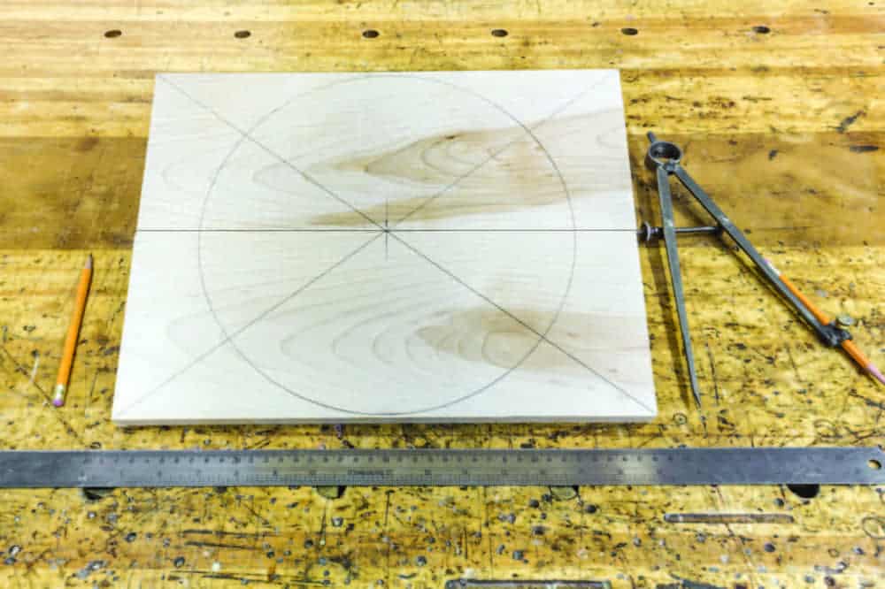
It’s now time to take the foot out of the clamps, sand it and draw an 11″ diameter circle onto the bottom side of the foot. Using a compass, pencil and ruler, place a center line and diagonal lines on the foot not only to find the center of the board but also to aid you in locating the position of the four rubber feet to be installed on the underside of the foot when the project is complete.
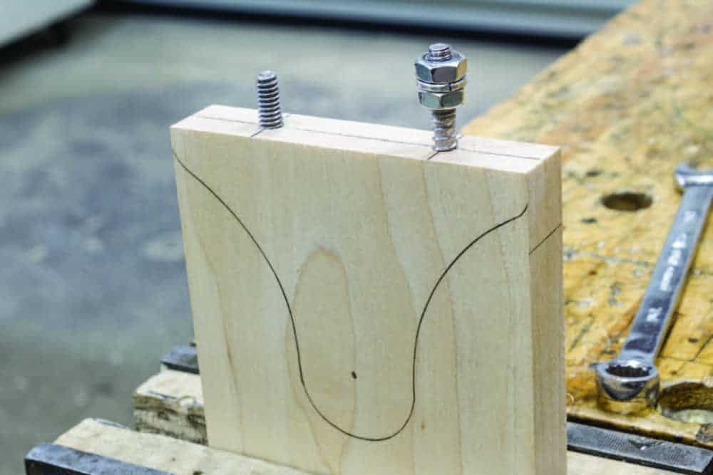
Before heading off to the bandsaw, there is one important step that needs to be done now; the installation of the two hanger bolts into one of the back supports. These 1″ long hanger bolts have a wood screw on one end and 1/4″ × 20 machine threads on the other. These hanger bolts and the 1/4-20 × 14mm connector caps can be purchased at any big box store.
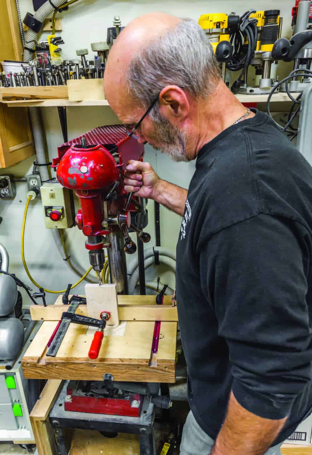
Depending on your choice of material, the pilot hole required for the wood-threaded portion of the hanger bolt will vary. Typically, a pilot hole from 17/64″ to 9/32″ in diameter works nicely, but it’s best to experiment on a scrap piece first. The hanger bolts are centered 2″ center to center on the 4″ wide back support. Drill the pilot holes in the end of the back support securely mounted on the drill press and then clamp it into a vise.
Using two 1/4″ × 20 nuts tightened against each other, carefully thread the hanger bolt into the end of the back support by using a wrench or socket and a ratchet. When done, you can remove the hanger bolts and cut the piece out on the bandsaw. Doing this operation now, as opposed to after the wood part is cut out, reduces the chance of splitting.
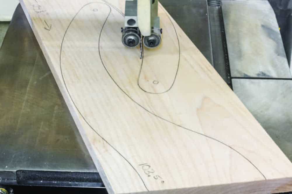
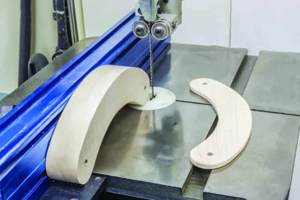
Cutting out the parts on the bandsaw is next. Cut as close to the line as you feel comfortable, remembering that you’ll need to sand to the line to get pairs of parts to match each other or to match the templates. During the sanding process, it’s a good idea to check your progress against the template, slowly sneaking up on the finished shape.
At this point you should have cut out all the 3/4″ thick parts and the 1-1/2″ thick upper arm and the semicircular base. The next step is to resaw the 1-1/2″ thick upper arm to an exact thickness of 1-1/4″. This thickness is critical. Check your bandsaw setup carefully by cutting a piece of scrap wood before cutting the project piece.
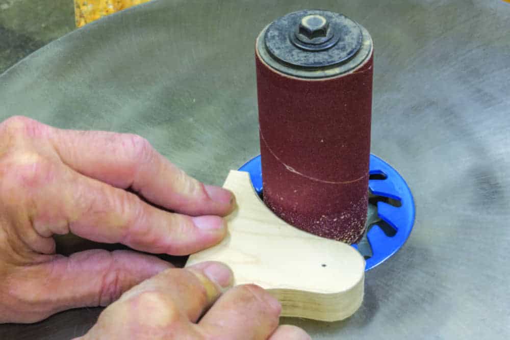
Once all parts are cut out, sand them to their final shape using an oscillating spindle sander or a sanding drum on a drill press to sneak up on the final shape using the template as a guide.
Drill some holes
It’s now time to drill the 1/4″ diameter holes in the upper and lower arms where indicated using a drill press. The upper and lower arms are 1-1/2″ wide at their ends and the 1/4″ hole needs to be centered on that width and 3/4″ from the end. Drill the hole in one arm and use that arm as a template to mark the other arm or stack the first arm onto the second arm and, using the hole in the first arm as a drill guide, guide the drill bit into the second arm. The result is two arms with perfectly matched hole locations. Use one of the lower arms in the same manner to drill the hole in the upper arms and back supports.
The foot assembly
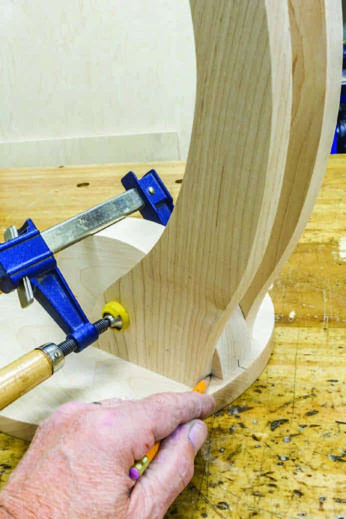
Using the center line on the underside of the foot, drill and screw the semicircular base to the foot, centered on that line so its edge is approximately 1/4″ from the edge of the foot. Clamp the lower arms to the base leaving approximately 3/8″ of the base exposed. Following the profile of the lower arm, trace the lower arm’s profile onto the base, disassemble it and cut that piece off on the bandsaw creating a flush base and lower leg connection.
Friction joints
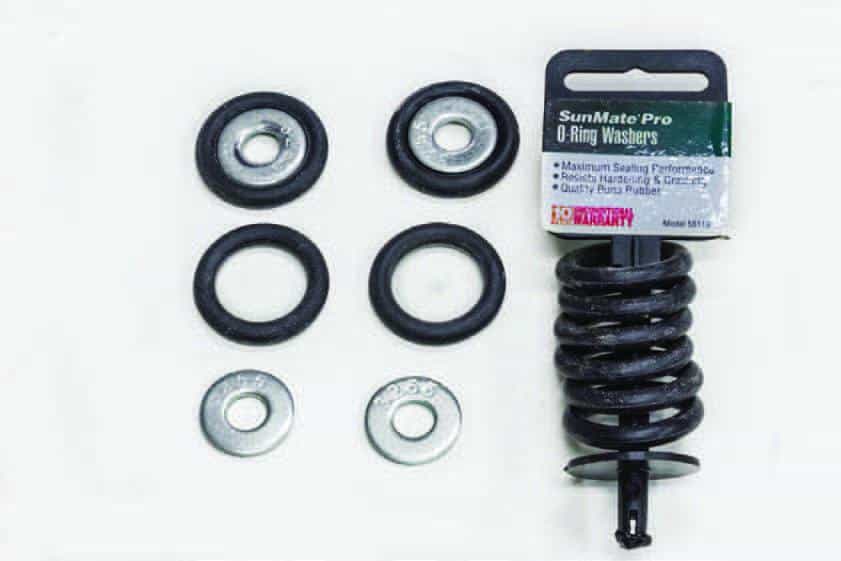
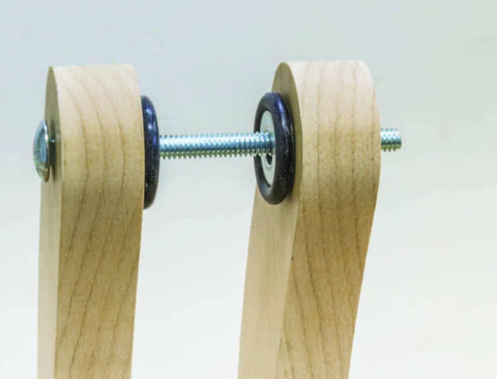
The joint between the upper and lower arms (the elbow joint) carries the heaviest load. Simply tightening that wood-against-wood joint will eventually wear and slip with repeated use. The solution is to employ some type of friction between the wooden pieces of the joint and that friction can be accomplished by using rubber “O” rings. Yes, the same rubber “O” rings used in your garden hose are ideal for creating non-abrasive friction within this tablet stand.
The outside diameter of a 5/16″ steel washer is perfectly sized for holding the rubber “O” ring while in use. Slip the “O” ring over the washer and they are ready to be installed in the joint.
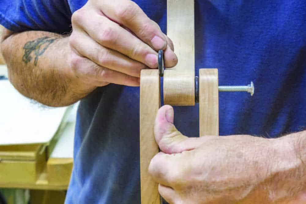
With the lower arms securely clamped to the base, try fitting the “O” rings with the 5/16″ washers and the upper and lower arm assembly together. You’ll find with just a little sideward pressure against the upper arms, you’ll easily manage to slide the “O” rings into place and the 1/4″ × 20 carriage bolt holds everything in place.
Sand, then initial assembly
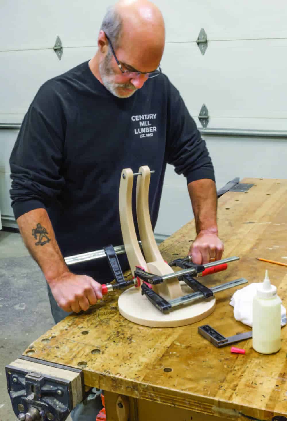
Now that you’re confident the elbow joint will work well, it’s time to glue and screw the lower arms and the base to the foot. Before doing that, take the time to break this assembly apart and sand each part thoroughly. Sanding these parts after assembly would be difficult. Now screw and glue the base to the foot. It’s important to slide a 1/4″ × 20 carriage bolt through the elbow joint in the lower legs to keep the arms parallel during the glue-up procedure. Glue and clamp the lower legs to the base and make sure the carriage bolt slides freely through the two holes in the lower legs. Beware of misalignment here and correct if needed.
Turn the assembly over and screw two 1-1/2″ × #8 wood screws through the foot, into the bottom of each lower leg, through the pre-drilled holes and put it aside to dry.
Head assembly
The head assembly is next, which includes the tablet’s upper and lower support, the back, and the two back supports. Depending on the size of your tablet, the upper and lower support, their routed groove, and the height of the back may differ from what you see here.
Re-install the hanger bolts into the back support. Remember those hanger bolts are exactly 2″ apart on center so you need to drill two, 3/4″ deep, 1/8″ pilot holes, center to center, on the other back support, perfectly mirroring the hanger bolt holes. With that done, assemble the back supports to the upper arm with a 1/4″ carriage bolt, flat washer, lock washer and knob handle. Don’t forget the “O” rings.
The 4″ wide back is next. Secure the back against the drill press fence and drill a 1″ deep, 1/4″ hole at the 2″ center mark of the back, making sure the hole is centered on the back’s 3/4″ thickness.
Now you’ll need to drill the holes in the face of the back for securing it to the two back supports. The holes in the two back supports are 2″ center to center so you’ll need to drill 4, 1/8″ pilot holes 2″ center to center and exactly 2-1/4″ apart. The left side holes are countersunk using a 3/8″ countersink bit for #8 × 1-1/8″ screws and the connector cap holes require a 3/8″ through hole with a 3/4″ counter bore, 3/16″ deep to recess the head of the connector caps.
With the previous 1″ deep hole drilled in the top edge of the back, you’ll now need to calculate the total length of the 1/4″ × 20 threaded rod required for your tablet. Use a long enough threaded rod to accommodate the upper support and knob and any different-sized tablets you may have at home. For my application, a total length of 2-3/8″ worked fine. Mix a small batch of two-part epoxy and adhere the threaded rod into the hole.
Temporally screw the back onto the back support using the #8 wood screws. Now slide the carriage bolt into the back support’s hole and slip the rubber “O” ring and washer onto the carriage bolt. Place the other back support into the holes for the connector caps. Feed the carriage bolt into the upper arm and slip the next “O” ring and washer onto it. Then slide the carriage bolt through the second back support. Carefully and slowly tighten the knob handle until the hanger bolts are centered in their holes and install the connector caps.
Install the lower support onto the bottom of the back using the same countersinking method you just used on the back-to-back support. Drill the 1/4″ hole in the upper support required for the threaded rod.
With everything assembled you’re ready to try it out. Notice how the washers secure the joints with very little effort. Adjust the elbow joint and the tablet support joint, making sure everything works smoothly.
Sand, then final assembly
Now you can sand all the remaining parts, glue and screw the back support to the back, and plug all screw holes with shop-cut tapered plugs or store-bought plugs and sand them flush.
I finished this project with three coats of oil-based polyurethane and spray painted the heads of the carriage bolts and the connector caps with black paint to match the rest of the hardware.
From its lowest position, the bottom of the tablet is 4-1/2″ off the foot and at its highest position the bottom of the tablet is 17″ off the foot. The head assembly rotates 180° giving you almost infinite adjustability. Whether you’re using a tablet as a student taking online courses, a budding chef tackling a new recipe in the kitchen, staying connected with family or friends, or just surfing the net, using your tablet now won’t be a real pain in the neck.
Photos by Gord Graff
Laying Out Curved Parts
Though not required to compete the project, Graff made templates of the parts in order to best use the material he had. Curved parts are sometimes tricky to work with, so the templates made that aspect easier.
Joinery, Then Breakout
Graff routed grooves in a few of the parts before breaking the parts out of the large piece of lumber. Small parts are hard to rout, while a larger workpiece is easier and safer to machine.
Rip to Width
With the tablet groove in them, you can now rip the parts to final width before trimming their curved ends on the bandsaw.
Angled Ends
Before breaking the lower arm ends from the blank, Graff trims their ends at the necessary angle. This would be hard to do once they’re cut from the blank because there would be no straight edges to reference.
The Benefit of Templates
Graff used the lower arm template to carefully lay out the two parts on the blank. Without the template, much more material would have been wasted. Notice the angled lower arm ends marked in pencil.
Hanger Bolts
Before cutting the back support to size, drill holes for the hanger bolts and install the bolts into their ends. Doing this now reduces the likelihood of the parts splitting.
A Round Foot
Some simple layout will give you the center point of the foot, along with the location of the four feet that will be installed later.
Cut Them Free
With the ends of the lower arms cut at the proper angle, it’s time to bandsaw the arms from the blank.
Upper Arm
Graff rips the upper arm to final thickness on his bandsaw. This part is too short to be dressed with a thickness planer.
Smooth Curves
A spindle sander makes quick work of smoothing the curves on many of these curved parts.
A Small Trim
With the parts positioned in place, Graff marks where the base protrudes beyond the two lower arms so he can trim that portion off with a bandsaw.
Garden Hose “O” Rings
To make a great friction joint between the upper and lower arms, Graff added an “O” ring to a standard 5/16" steel washer. When the joint is tightened the tablet will be fixed in place.
Start to Assemble
Once they’re machined to size, the lower arms, base and foot all get permanently secured together.
Threaded Rod
Graff bores a hole to accept a threaded rod in the top of the back. The threaded rod will allow the user to tighten the hardware to provide downward pressure on the upper support to keep the tablet in place.
Tricky Spot
A bit of careful placement will allow you to position the “O” rings and washers in place and bring that joint together.
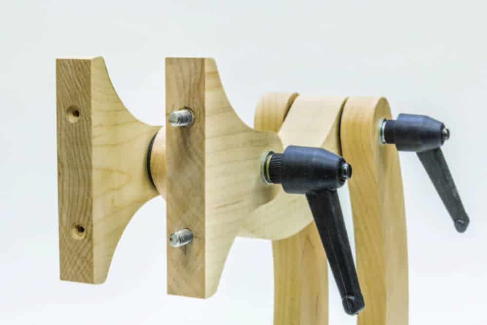
Almost Done
The assembled back support joint showing how the back will fit onto the threaded rods and get fixed in place. The two black handles control the position of the tablet and lock it in place.
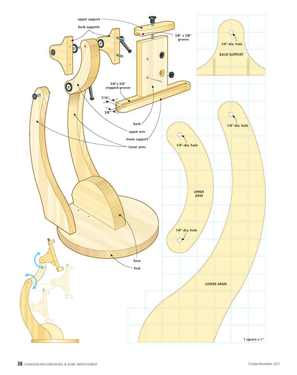
Illustration
Materials list
Hardware list
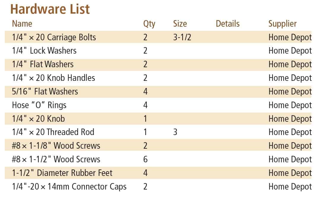
Illustration by Len Churchill


Is it possible to get template for this project?
All that is available are the illustration, material list and hardware list Elsie.
Hi, I really like your adjustable table stand.
One thing that I would like, is having pictures of the scale size of the parts .
Thank you
A minor quibble: the Hardware List displays the Materials List.
Also, are the templates available as files (svg, or the like) so I can do this on my CNC?
Thanks
Larry
Thanks for the heads up Lawrence. A glitch that we’re working on. No SVG files I’m afraid.
Thanks, Gord. So sounds as if the hanger bolts give some extra needed rigidity and strength. I will send a photo or two when its all done!
Hello Mark,
Glad you like the design and Douglas fir sounds like a great material for your project.
If the back was attached to the back supports with glue and 4 screws, installing that assembly along with the rubber and metal washers onto the upper arm would challenging to say the least. To make assembly easier and for future rubber washer changes, I chose to use two hanger bolts. Certainly you could use four hanger bolts if you like the finished look. I hope this answers your question.
Why not send in a photo or two of your finished project, I’m sure others would like to see it, I certainly would.
Regards
Gord
Great design! I’m planning to build one using Douglas-fir. One question: I don’t understand why the hanger bolts are used on one side of the back support. Why not both sides? Why not just use wood screws?