PROJECT
Heirloom dresser

Marty Schlosser

Find more Furniture projects
Building a dresser can be a challenging undertaking, if only because of the numerous pieces and the variety of joinery techniques involved.
However, if you take it ‘one joint at a time’, it’s a relatively straightforward project, within the scope of any woodworker with intermediate level skills.
When I set out to build this dresser, there were two things I wanted to achieve. First, I wanted to provide for plenty of storage while retaining pleasing proportions. To achieve this I incorporated fewer, yet larger drawers than is typical for similar sized dressers, and I used the Golden Ratio to establish the drawer sizes so they would appear balanced. Second, as with all my projects, I wanted this to be an heirloom piece that would last for generations. I chose to use materials of the highest quality, incorporating proven joinery and taking the utmost care in assembling the project. However, I departed from tradition on a few points. I used full-extension, self-closing drawer slides rather than wood-on-wood slides. Metal slides are very reliable and the style I chose stay unobtrusively hidden underneath the drawers. If you elect to use different slides, you may need to adjust the drawer box dimensions accordingly. I also used a water-based finish, as the impact upon the environment and my health is minimal in relation to their oil-based counterparts.
Heirloom dresser
Some Practical Considerations
The primary wood for this project is cherry, which I elected not to cover with a stain. I carefully selected boards whose hues and shades would go well together when finished. For the secondary wood I chose yellow birch because of its lower cost and similar characteristics to cherry. Other good secondary woods include alder, poplar and beech. When I am not using stain on a project I purchase about 20% more stock than my materials list calls for. This allows me to use only the most interesting and visually pleasing sections of the boards. I also use the less desirable pieces of the primary wood as secondary wood. Whenever possible I purchase the wood a few weeks before I begin working on the project, to allow the wood to acclimate to my workshop’s relative humidity. I also purchase all the hardware that I will need before I begin construction.
A day or two before I begin work on the project I check my machinery and hand tools to ensure they’re cutting accurately and cleanly. I have a collection of high-quality set-up tools and sharpeners to deal with this important task, but will have my sharpening service look after those blades and knives that I can’t deal with myself.
This project calls for a number of different joints: sliding dovetails, half-blind dovetails, mortises and tenons, and half-lap (bridle) joints. You could substitute some of the joinery techniques I used, but make sure that you don’t compromise the structural integrity of the piece, and that you allow for seasonal movement of the members. In building up the three panels I used biscuits; not a traditional joinery technique, but one that is both practical and effective.
The most frequent joint I used was the mortise and tenon. I milled all the mortises 15/16″ deep, and the tenons ⅞” long. This provides compression room for the glue. Remember that tenon length is not as critical as tenon width, as you want a lot of gluing surface. Make sure the tenons are about 1/32″ thicker than the mortise width. That way you can hand fit each of them individually to account for any variances that inevitably creep into the equation. To fine-tune the tenons I use a router plane, which is easy to use and helps ensure that tenon faces are parallel to their board’s faces. This goes a long way to ensuring tight-fitting mortise and tenon joints.
There are two schools of thought for dealing with the inevitable excess glue that will ooze out of joints: carefully wipe it off with a water-dampened cloth right away, or scrape it off with a chisel or knife once it’s set up a bit. I use a damp cloth, as I find it very difficult to get everything scraped off, once the glue starts to set up.
Careful Stock Preparation Pays Big Dividends
On most projects I cut and plane all boards oversized – about ⅛” thicker and ¼” wider and longer than called for. I then leave them at least overnight to allow any stresses inherent in the boards to show themselves before milling them to their final dimensions. To ensure all like pieces will be the same sizes, mill them at the same time before readjusting your machine settings. Make sure that you sticker the pieces to allow for adequate air flow, and don’t leave them on a concrete floor, place them on a workbench or table. I also use chalk or pencil to mark which sides will be facing ‘in’ and ‘out’.
You may find it useful to make spares for those pieces that have complicated joints. The spares will not only come in handy if you make a mistake, but provide you with stock on which to practice your joinery before committing to your final project pieces.
Legs and Rails Provide Rigid Structural Support
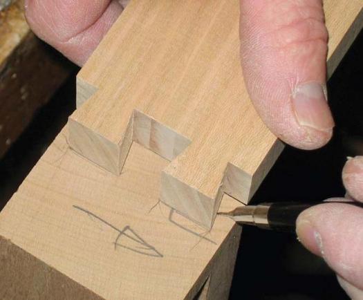
I use high-quality layout tools and a knife to precisely mark my layout lines. Highlighting the knife-cut lines with a mechanical pencil that has a .5 mm lead will cause the lines to show up better. I also find that good task lighting and magnifying binoculars are helpful. To cut the sliding dovetail joints I use a light-duty shaper armed with a ½” shank dovetail bit, but you could accomplish the same on a router table. Remember that tear-out can be a problem with dovetail router bits, so you may wish to either use a backer board, or to pre-score the cut lines with a sharp knife.
• Cut the pieces for the six legs (A, B, C) and rails (D, E, F) to dimension.
• Lay out and cut half-blind dovetail pins on the top of the corner legs (A) and matching tails in the top rails (D).
• Lay out and cut sliding dovetail pins on the inside face of the corner legs (A) and matching tails in the lower rails (E, F).
Dovetail joints excel at preventing the sides from racking. I cut the tails in the top rails using the same router bit height setting I used for the sliding dovetail tails on the lower rails. This helps everything line up correctly when assembly time comes around. I hand cut the mating pins in the top of the corner legs. Although this is a time-consuming task, if your tools are sharp and you take your time, it’s relatively straightforward. If you are uncomfortable cutting dovetails, you can mortise the rails into the legs, and then reinforce them with brads or dowels. However, the resulting joint would not be quite as solid.
• Cut double through mortise and tenon joints to join the top rails (D) with the center legs (B, C). I prefer to cut the mortises first, and then make the matching tenons. You can cut these by hand, or use a router.
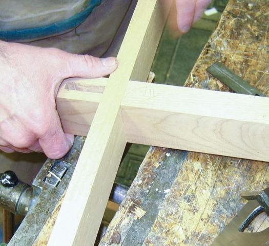
• Cut half-lap joints on the center legs (B, C) and lower rails (E, F). A bridle joint is good at supporting heavy loads and it’s relatively easy to cut. You’ll be glad you made extra pieces so you’ll have something to help set up your saw to cut the joint precisely, because it’s very easy to make these joints too loose.
• Cut a taper on the bottom of the legs. I used a tapering jig on the table saw for this, but you could do it by hand or on the band saw.
Stretchers Serve to Unify the Leg and Rail Assemblies
• Cut the pieces for stretchers (G, H, I, J, K). They support the drawer sliding hardware. Put the top stretchers (K) aside for now.
• Lay out and cut the mortises on the corner legs (A) that accept stretchers (G). The mortises are centered on the width of the legs.
• Lay out and cut mortises in the corner legs that accept stretchers (H). Position the mortises so that the stretchers will end up flush with the inside faces of the legs.
• Lay out and cut the mortises in the center legs (B, C) that accept the center stretchers (I, J).
• Lay out and cut the tenons on the stretchers (H, I, J).
• Rout a ¼”deep rabbet on the inside bottom edge of the lower side panel stretcher (G), and the top inside edge of the lower rails (E, F) to accept the dust panel (P).
Glue Up the Solid Wood Panels
The two side panels (N) and the top (O) are relatively straightforward to glue up. Be sure to use creep-resistant glues, such as West System Epoxy or Titebond III. I also prefer to use biscuits, spaced about 8″ apart, between each of the boards that make up these panels.
Biscuits not only help to align any wayward boards during glue-up, but contribute to panel integrity throughout their life. I mark biscuit locations on the side edges of the panels when I glue them up, just to ensure I don’t cut through any biscuits when I cut the panel to final length.
Apply a finish to the solid wood side panels (N) before gluing them into their framing, as it’s next to impossible to ensure that finish will find its way to the innermost reaches of the panel edges once they’re inside their slots. Failing to finish the panel edges could result in unsightly unfinished edges showing when the panels shrink during the drier times of the year.
Deep Grooves Accommodate Solid Wood Panel Expansion
• Dry assemble and clamp both sides – corner legs (A) and stretchers (G). Using a roman ogee bit with a bearing guide and rout a decorative edge on the outside of the assembly.
• Using a ¼” wing slot-cutting bit with bearing guide, rout 17/64″ x 1″ grooves in the corner legs and 17/64″ x ¾” grooves in the side stretchers to accept the side panels. Tear-out can be minimized by making a shallow climb cut first, being careful the router doesn’t get away from you. Once this preliminary slot has been made, you can proceed with plowing the rest of the slot without much likelihood of tear-out occurring. Solid wood panels will expand and contract in relation to changing humidity levels throughout the year, and the grooves in the legs need to be deep enough to provide ⅜” of expansion depth on each side, once the panels are in place.
• Dismantle the side assemblies and square up the corner sections with a chisel to ensure the side panels will have the expansion space they require.
• Mill a tenon on all four sides of the panel (N). I used a roman ogee panel raising bit with guide bearing to mill the outside face and a straight bit to mill the rabbet on the inside.
Stiles Separate Top Drawers
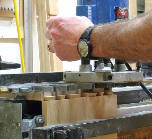
• Rout dovetail tails for the front and rear drawer stiles (L, M). Practice cutting these joints first on spare pieces, if you milled some, otherwise cut the rear stiles first. That way you’ll have the settings dialed in by the time you do the front ones, which showcase your craftsmanship – for the life of the cabinet.
• Rout matching pins on the bottom face of the top rails (D) and topmost lower rails (E), into which the stiles are housed.
• Cut mortises in the inside of the stiles (L, M). These stiles are joined by stretchers (K) that serve to support the drawer slides. (If you elect to use traditional wood-on-wood slides, you’ll also need to incorporate a stretcher to join the front and rear rails below each drawer slide.)
• Cut matching tenons on both ends of the stretchers (K).
Dust and Back Panels
A test fitting of the carcass will both confirm that everything’s going to fit properly when it comes time for the glue-up, as well as enable you to establish and mark the exact locations for the rabbets that will accommodate the back panels and the bottom dust panel. Take your time and document the process so things will go more smoothly when the final assembly happens.
• Rout rabbets on the inside edge of the two back corner legs to accommodate the back panels (Q). Don’t forget to stop the cuts in the legs and finish them off with a chisel.
• Cut the back panels (Q) and bottom dust panel (P) to their final dimensions. Don’t be surprised if, despite your attention to detail, the two back panels’ widths are slightly different. Such is life when working with large, solid-wood framed cabinets.
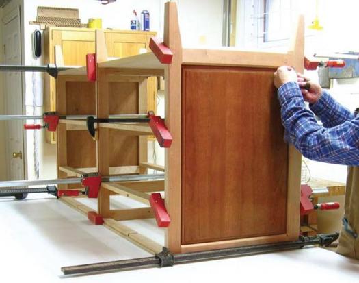
Assembly Is Where It All Comes Together
In preparation for gluing, make sure you have all the clamps you’ll need on hand and set to their approximate widths. Also get a container of water, some rags and a dull knife at the ready, to help clean up any excess glue that’ll surely ooze out of these tightfitting joints. Make sure your glue bottle is full enough to see you through to the end of the glue-up. Get the framing pieces arranged in some semblance of order, so you won’t be scratching your head when you should be proceeding with the glue-up. With a project this big you might want to have a helper assist you.
• Start by gluing up the front framing. Glue the three lower rails (E) into the center leg (B), then glue the dovetail tails into the front leg (A) matching dovetail pin slots. Work on one corner leg at a time until you’re happy with everything to this point.
• Glue the upper rail (D) into place next, followed by the two upper drawer stiles (L). If you’re dry-fitting went well, this should proceed without difficulty. Remember to deal with any glue squeeze-out as it comes along. Check your diagonal measurements to ensure the frame is square, and then check it for flatness by sighting along the edges of one leg to the next. While the glue is still setting, check for any discrepancies.
• Once the front frame is dry, glue up the back frame.
• Place the front frame face down on the glue-up table. Working on each side separately, place stretchers (G) part way into their mortises, then set the side panel (N) into position. Ensure you have the panel oriented correctly as you insert it. You should be able to push the stretchers fully into their mortises without too much difficulty. But if things balk, be willing to use a clamp to move things along.
• Insert the two side stretchers (H) into their respective mortises.
• Follow the same process for the other side, and then set the center stretchers (I, J) into their mortises. Stretchers (K) are the last ones to be put into position.
• Position the bottom dust panel (P) into its rabbet in the lower stretcher of the front frame before setting the rear frame over the upright stretchers. Once things look like they’ll line up, with the assistance of someone else, turn the frame onto its top so you can more readily work things together. Working deliberately, yet patiently, from one side to the other, push the frame slowly into position until all of the tenons are fully seated against the shoulders of their corresponding mortises. Don’t become frustrated if the glue-up requires you to use clamps to bring things together: the tight-fitting mortise and tenon joints you so carefully fine-tuned by hand can take a bit of ‘English’ to bring them together. I put a bar clamp near every stretcher to ensure everything stays together, and then I take the time to check the diagonal measurements – in both planes – to make sure things are square. Go over every joint and deal with any glue squeeze-out that shows its ugly face.
Fasten the Cove Moulding to the Top Rail
The cove mouldings (EE, FF) that fit underneath the edge of the cabinet top lend an air of substance to the top, without making it appear overly heavy.
• Plane a wide, straight piece of stock to ⅝” thickness, then machine the cove using a ½” cove bit in your router table or shaper.
• Rip the moulding to its final width of 1 ⅛” then cut the required three pieces a bit oversize so you have enough length to fine-tune the mitred corners until they fit perfectly.
• Fasten the moulding into place using glue and brad nails.
Drawer Boxes
For this project I built the drawer fronts separately from the drawer boxes. This greatly simplifies the whole process – from construction to insetting them into the cabinet frame. Although I elected to use dovetail joints to make the boxes, you could substitute rabbet or locking joints at the corners. If you’ve decided to go with the dovetail option, make sure to place the lower pins so they’ll cover the slots that will accept the drawer bottoms.
• Mill the drawer sides (R, T) and fronts and backs (S, U).
• Mill the drawer bottoms (BB, CC).
• Cut the dovetails.
• Dry fit the drawers to make sure the bottoms fit. Cut the drawer bottoms only after you’ve made sure the measurements will work.
• If you’ve elected to use the same hardware slides as I did, you’ll need to cut the drawer slide clearance slots and drill the hole they need in the drawer backs (S, U). Refer to the manufacturer’s instructions.
• Finish sand the interior of the drawer box pieces. Be careful not to sand where the joints come together, or their tight fit could be compromised.
• Glue up the drawer boxes, but don’t put any glue in the slots that house the drawer bottoms. I like to round over the top of the drawer box sides and back, and the inside top of the drawer box fronts with a ⅛” round over router bit. This simple touch makes the drawers look more finished.
• Sand the outsides of the drawer boxes and screw on the underside locking catches designed to affix the drawer boxes to the hardware drawer slides.
Make the Drawer Fronts
The drawer fronts consist of a plywood panel (V, W), rabbeted into a mitred frame (X, Y, Z, AA). The inside edges of the frame pieces are machined using a roman ogee bit, and the bead is also routed out. I do these operations before ripping the rabbets on the table saw.
• Mill sufficient moulding stock for the drawer frames (X, Y, Z, AA), and the feathers (DD).
• Measure all the drawer front openings on the cabinet frame so you’ll be able to make whatever adjustments in the frame lengths as may be needed to have the drawer fronts fit precisely.
• Cut the mitre joints.
• Dry fit all the drawer front frames and measure the exact sizes you will need for the front panels (V, W).
• Mill the front panels. Mark the drawer number and an arrow showing which edge is up, on the back of each panel. This way there’ll be less likelihood of getting the panel order mixed up when it comes time to place them with their respective framing members.
• Glue the frame pieces together around their matching panels. Once dry, cut the slots for the mitre joint reinforcing feathers (DD), then glue them into place. It’s amazing how such thin pieces of wood will keep mitre joints from opening up due to fluctuating humidity conditions.
Finishing and Fitting the Drawers
Apply the finish before the assembly goes any further; it’s easy to get inside an unassembled cabinet with a brush or spray gun. Finish everything, including the drawer boxes and fronts, as well as the back panels. Laying down the same number of coats on both sides of everything will do much to keep warping at bay. I apply most of my finishes with a HVLP spray system. I can apply the finish quicker and get a much better look than with brush or rag (see HVLP Finishes sidebar).
• Install the sliding drawer hardware. These slides should be placed approximately 1 ¾” back from the front of the cabinet and fastened to the stiles with #7, ⅝” flat head screws.
• With the slides in position, install the drawers, one at a time, beginning with one of the bottom drawers. Slide the drawer box into position until the latches underneath the drawer boxes engage and the drawer is at its back-most position.
• Select the matching drawer front and place it inside the drawer opening. Hold the drawer front centered in the opening; there should be approximately 3/64″ of space on every side. Lightly clamp the drawer front and the drawer box front together (the clamp should fit over the framing above the drawer you’re working on). Readjust the drawer front position until it’s centered as closely as possible, then tighten up on the clamps. The drawer fronts are fastened into place with a pair of screws from the inside of the drawer box. Remember to countersink the holes and make sure you use a screw that’s the proper length, as you don’t want to have them go through the front of your drawer.
• Drill the hole for the drawer knob from the outside and put the knob into position.
• Continue working your way across and up, until all eight drawers have been properly fitted into position.
HVLP Finishes
If you only need to apply a finish occasionally, or if your projects tend to be quite small, then the standard methods of application – brush or rag – should do perfectly well for you. However, if you produce a lot of product, or if you make your livelihood woodworking, then a HVLP spray system, like the Fuji Mini-Mite 3 (fujispray.com), is well worth considering. Environmental and health concerns, as well as the desire to save money by reducing industrial overspray, lead to the development of HVLP (High Volume, Low Pressure) technology. A HVLP system is affordable enough for the small shop owner, the serious hobbyist and the casual builder. Essentially this system works in the opposite way a standard compressor driven gun works. A turbine provides a high volume of air at a low pressure to the gun. HVLP systems are portable, so you can use them anywhere and they are easy to store, they significantly reduce the problem of overspray, they make efficient use of your finishing supplies, and they reduce the time required to finish a project. For more information see the Resources listing below.
Attach Top and Back Panels
The top (O) is fastened to the cabinet with three rows of screws: front, middle, and back. The front ones are meant to keep the front firmly in position, even when the top changes dimension over the seasons.
• Drill countersunk pilot holes for these six screws from underneath the top front rail (D). The middle row of screws is held in place with brackets that allow for about ½” of movement, to keep the cabinet top from splitting. I made these brackets using some heavy brass sheeting that I keep on hand for such purposes. Use either pan-head screws or put a washer under the tapered head of the screw, so the screw can slide as necessary, yet hold the top firmly in position.
• Set the back row of screws so as to allow the top to move about ⅝”. Rout five slots approximately ¾” long and ¼” wide in the top rear rail (D) to accept these screws.
• Drill holes for the #6 – ⅝” screws, and then fasten the back panels (Q) into place.
Congratulations, you’ve made what should become an heirloom quality dresser. Now, sign and date the back of the cabinet so that your great-great-grandchildren will know who made it for them.
Cut taper on bottom of legs
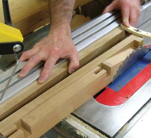
Half-lap joint – rail and leg
Routing tails on drawer sides
Mark out half-blind dovetail on corner legs and rails
Gluing up the carcase
Dresser side
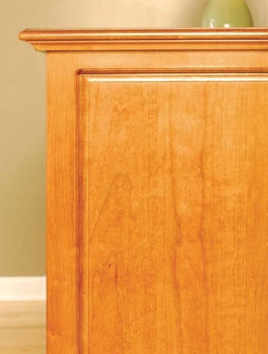
Illustration by James Provost