PROJECT
Build track saw parallel guides

Steve Der-Garabedian

Find more Jigs projects
One of the tasks track saws excel at is cutting down sheet goods, but it’s often difficult to quickly and accurately align the track parallel to a workpiece’s edge, especially for repeated cuts. These simple guides solve that problem.
I use a lot of plywood for making cores for the veneering I do, and needed a way to cut the plywood accurately without breaking the bank on manufactured guides. These guides allow me to easily cut parallel to the factory edge. Even when the factory edge isn’t perfect, I can set these jigs slightly wider and then come back and clean up that not-so-perfect side. Other times, I need several pieces all the same size and these guides make quick work of that, too.
Build track saw parallel guides
Accuracy breeds accuracy
Any jig that needs setting to a dimension needs to be made accurately. In this case, the ends of the rails need to be square and the measurement setting guide accurate to transfer the proper width of cut. This isn’t difficult using well-made plywood such as Baltic birch.
Start by gathering your hardware; T-bolts, washers, nuts, knobs and aluminum T-tracks. I chose the 24″ length as this is the most useful size for my work. You could make these as long as you’d like, depending on your shop needs. While the measurement setting guide isn’t absolutely necessary, I feel for the small amount of extra work it takes to make, you get an accurate way of setting the guides. You could also make this jig without the aluminum tracks, but I think they add a level of accuracy, give the guides a clean look and makes them easier to use.
Time for some milling
All the pieces are cut from a small section of 9/16″ or 14mm Baltic birch. You could get away by using 3/4″ or 19mm thick plywood, as that would leave much more material under the T-track to work with. Cut the pieces for guides, adjusting the length to make the rails longer if you’d prefer.
The T-tracks fit in slots cut into the rails. A router works nicely for this task. Use a 3/4″ router bit and cut to slightly over 3/8″ deep in a few passes. I cut the slots to a length of 25-1/2″ which gave me 3/4″ on each end to slide the T-bolt into the rail once assembly started. Also, the routed slot starts 1″ from one end of the plywood rail. The slot for the measurement setting guide rail is just as long and deep, however, increase the width to 1-7/16″ to accept the wider T-track. I used the same 3/4″ bit and adjusted the fence after the first pass to make up the difference. All of these grooves are machined so they’re centred on the plywood rails. I also chose to square the top and bottom of the slot in the measurement setting guide rail for a cleaner look. You could do the same for the main rails but I liked the rounded look on them.
Getting sticky
I used an epoxy with a 20-minute set time to fix all three tracks into their respective slots. Since they sit slightly below the surface of the rails, I cut some narrow strips of MDF to fit into the slot in the track to help apply pressure and ensure the track was fully seated in the groove. I applied the epoxy and clamped the tracks while the epoxy set. For the wider measurement setting guide, I used a wider piece of MDF to better spread the clamping force. Have some rubbing alcohol and shop towels ready to clean any epoxy squeeze-out before it hardens.
Slip and slide
Use more of the same plywood to make the sliding assemblies. Cut the pieces to size, according to the cut list. I added an angle to the side of the wings. Since the wings are small, I cut them on the bandsaw and cleaned them up with a block plane and some sanding. They don’t need to be perfect. These relief cuts provide a good visual indication of which side to register the guides to the track.
To assemble the sliders, first take a small piece of wax paper and slip it over the rail and under the wings. Use a clamp to hold the wings tight to the rail. Next, place the top flush with the sides and front of the wings. Apply glue to the bottom of the slider top, then use a pin nailer to attach it to the wings. Avoid placing glue where it contacts the rail, and as an added bit of security countersink a #8 × 1″ flat head wood screw on each side of the top into the wings.
Next, I set the bottom registration piece back from the front equal to the width of an engineer’s square blade (3/4″) and secured it to the rest of the assembly with two #8 × 1″ flat head wood screws. Don’t use glue here, as the bottom needs to be removed for final assembly.
Drill, drill & drill
Repeat the steps above two more times. Once the assemblies have been made, fine tune their movement by sanding the rails. It shouldn’t take much, and a small amount of wax will also help them move. It’s now time to drill holes into the tops to allow the T-bolt to pass through. Mark the location of each hole over the centre of the T-track and in the middle of the top. Using a sacrificial piece between the wings and a 1/4″ brad point drill bit, drill these through holes.
Final Assembly
Once all the pieces have been drilled and sanded it’s time for final assembly. Slip a T-bolt into the T-track and place the top half of the sliding assembly onto the rails, capturing the bolt. Place a washer on top, then the knob and tighten it down. Screw the registering bar back onto the bottom.
In order to install the measuring tape onto the measurement setting guide, cut a shallow 1/32″ deep groove into the top of the rail, in line with where the tape is located on the T-track. This groove will just be the extension of where the measuring tape is located in the T-track. Line this up and use a router to cut this groove. In order to accurately stick the tape, measure and lock in the slider 5″ away from the top. You’ll also have to adjust for the kerf of the saw, as the saw will cut about 1/8″ into where the guide rails were. Make sure this measurement is to the bottom registration bar. Next, peel and stick the tape, keeping the correct distance from the mark at the front of the slider’s top.
Using the guides
The guides are easy to use. To set them for a specific cut – let’s say 6″ – slide the assembly to the 6″ mark. Next, take one of the guides, loosen the knob and register them bottom to bottom. Slide the assembly up and tighten the knob. You can set the second guide in the same manner, or register it against the other guide.
Clamp the guide rails to the workpiece, butt the cut-side of the track against the end of the rails, clamp it in place, remove the guides and make your cut.
Using a track saw with jigs makes it not only easier, but also more accurate. These guides are easy to make, won’t break any budgets and don’t take long to make. Now you can make parallel cuts all day long.
Illustration

Material and Hardware List

Photos by Steven Der-Garabedian
Hardware First
Assembling the hardware before you begin is usually a good place to start. That’s especially true when working with T-track and other jig parts.

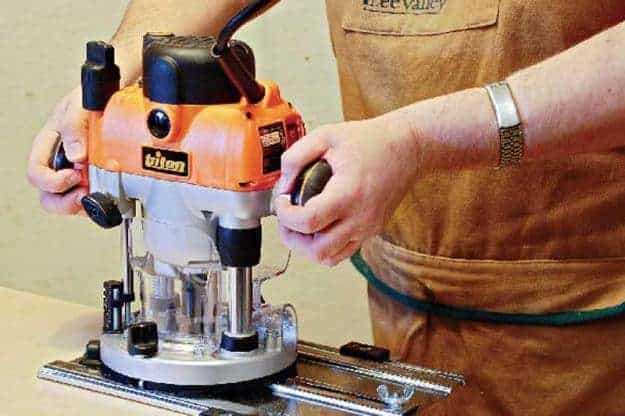
Getting Groovy
A router bit leaves a groove the correct width to accept the T-track, and the small area at either end of the track can be used to insert the head of the T-bolt.

Glue It Up
Although not a lot of pressure is needed, it’s important that the pressure is even along the length of the T-track while the epoxy dries. Der-Garabedian used a narrow strip of MDF in the T-track goove to allow him to better apply pressure with the clamps.

Square It Off
Der-Garabedian chose to chisel the ends of the wider groove square for aesthetics. He left the ends of the narrower routed groove round.

A Different Caul
A wider piece of MDF scrap was used as a caul to help seat the wider T-track in the measurement setting guide rail. Der-Garabedian cleans up any epoxy squeeze-out before it cures. The T-track stops 3/4" away from the end of the groove so the head of the T-bolt can be inserted into the track.

Notched Wings
Although it’s more for aesthetics than anything, Der-Garabedian notched the outer corners of each wing in the sliding assembly before securing them together.

Pin It in Place
Pins will hold the parts of the slider in place until a few screws can be added. Wax paper will keep adhesive off the guide rail while bringing assembly together.

Secured for Good
Screws secure the wings to the upper part of the sliding assembly.

Add a Lip
When attaching the lower end to the sliding assembly, ensure the edge of the part is set back 3/4" from the wings. This provides a lip to reference the slider off when setting the cut width.

Through Hole
A hole needs to be bored through the slider assemblies to accept the T-bolt. Align the hole with the location of the T-track in the rail, which should be centred on the part. Double check that’s the case before you bore the holes.

Mark the Location
Here, Der-Garabedian is marking the location of the 1/32" deep rabbet in the guide rail that will accept the adhesive measuring tape.

Set the Dimension
In use, Der-Garabedian uses the measuring gauge to set both of the guide rail assemblies. This ensures each assembly is the same dimension.

Accuracy Is Important
When securing the measuring tape in place, be sure to place it so it reads accurate measurements when the jig is in use.

Illustration by Len Churchill


Would not a fence attached to the saw make more sense for parallel cuts?