PROJECT
Build a garden tote

Rick Campbell

Find more Outdoor projects
Keeping all your seeds and planting tools organized and within arm’s reach makes gardening even more enjoyable.
As spring approaches, my thoughts soon turn to the garden and getting my hands back in the soil. What I don’t look forward to is the annual ritual of digging through the garden shed to gather all the tools and supplies needed to get the planting process underway. Well, that won’t be a problem this spring because I built this handy seed-starting tote to keep everything organized and ready to go.
The partitioned tray on top has plenty of room for all my gardening hand tools and the base underneath has more than enough space to arrange my entire inventory of seed packages. A wood latch connects the tray to the base so the entire unit can be picked up by the handle and carried around. If you’re not into gardening, this versatile tote could also carry hand tools and hardware when doing minor repairs around the house.
Build a garden tote
Tray and base construction
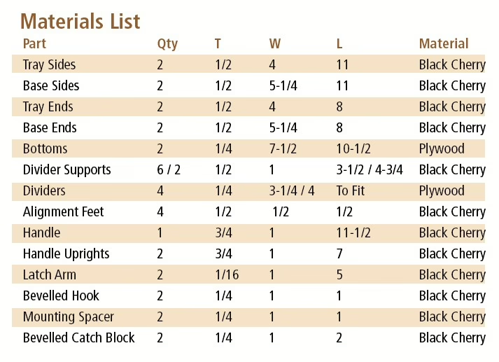
I built my tote out of cherry because I love its rich tone and beautiful grain pattern, but you can construct yours out of any species you happen to have on hand.
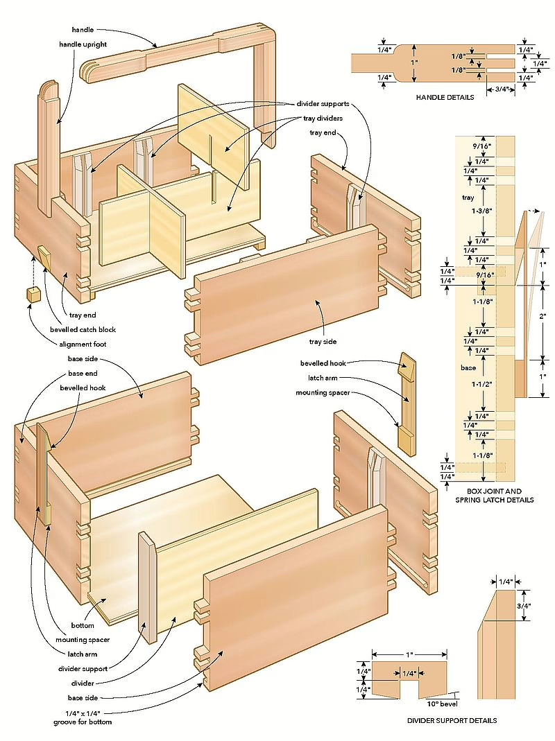
Begin by preparing enough 1/2″ thick stock to make the side and end panels for the tray and base, then cut the parts to size. I used sturdy box joints to assemble the corners of my project, but many other joints will also work if you want to simplify or adjust the construction process. A box joint jig will go a long way to assisting you with making this exceptionally strong and nice-looking joint. My jig is more complex than most, though any box joint jig can help you machine these joints, as long as you set it up properly.
Regardless of the method you follow to make box joints, I have a few tips that may help to up your game. First of all, double up the side and end panels to speed up the process and always use a backer board to prevent unsightly tear-out. It’s also good practice to make the slots a hair deeper than the thickness of the connecting pieces so the ends of the interlocking fingers can be sanded perfectly flush after assembly.
After preparing the box joints, your next task is to mill 1/4″ wide by 1/4″ deep slots in the interior walls of the base and tray parts to receive the bottom panels. For the long side panels, the dadoes can extend the entire length of the parts, but you need to stop 1/8″ short of the edges when completing the grooves for the end panels. If you don’t, the gap on the end of the dadoes will be visible when you assemble the joints.
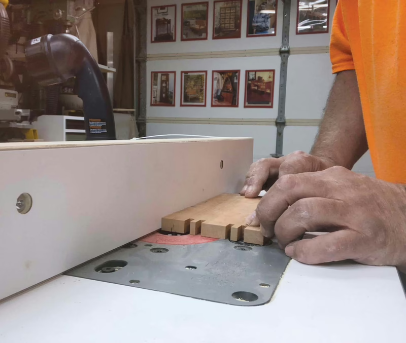
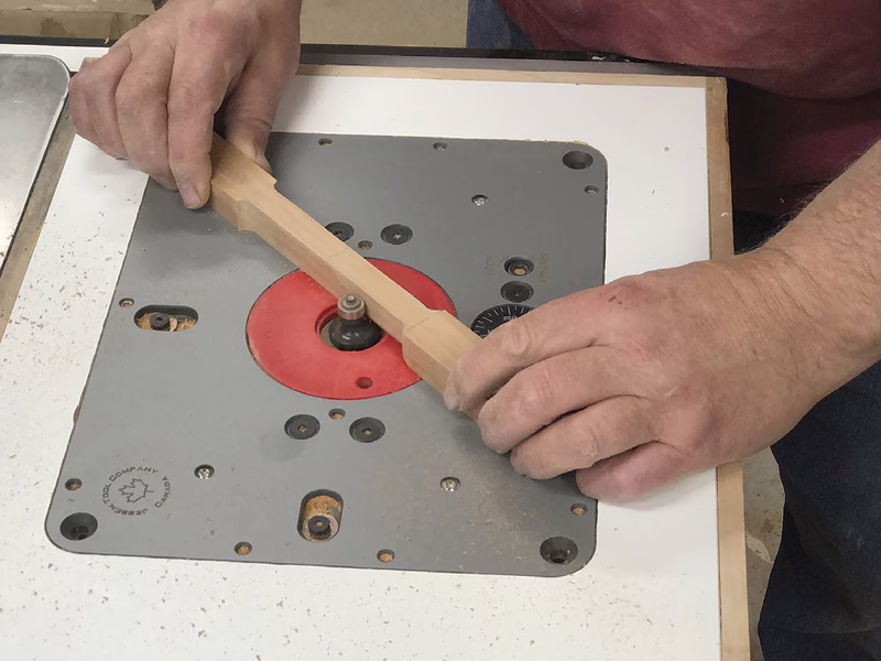
I prepared all these dadoes using a guide fence and a 1/4″ diameter straight bit installed in my router table. Don’t attempt to complete the procedure in a single pass or you risk overburdening the router, scorching the bit, getting a poor cut or worse. A better strategy is to make a series of progressively deeper passes until the final 1/4″ depth is achieved.
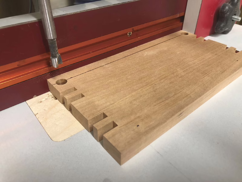
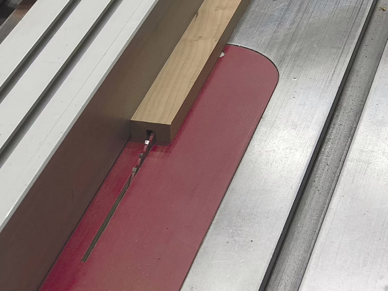
The full-length dadoes for the side panels are straightforward, but the stopped dadoes on the ends can be a bit tricky. Typically, stopped dadoes involve plunging the part over a rotating straight bit to begin the groove and lifting the piece off the bit before reaching the end. If you’re using a proper plunge router bit and are knowledgeable and comfortable with this operation, great, but I’ve never been comfortable with the idea of pressing a piece of wood onto a shaft of sharp spinning metal. Instead, I follow a slightly modified approach. I start by using a flat-bottomed Forstner bit with a slightly wider diameter than the width of the slot to make a 1/4″ deep pocket at the beginning and end of each slot location. For this application, these holes are located 1/8″ from the edge of the parts.
Next, I position the router fence and set the bit height for the initial shallow pass. When all of this is ready to go, I place the pocket I drilled on the front end of the workpiece over the bit and hold the part firmly against the fence as I turn on the router. It’s best to check that the bit freely rotates with the workpiece in place before you turn the router on. With the router on, I slowly guide the part over the bit until I feel it break through the wall of the pocket on the other end. Continuing to hold the part firmly against the fence, I turn off the router and let the bit come to a complete stop before picking up the workpiece. I progressively raise the bit and repeat this process until I reach the full 1/4″ depth.
Bottom panel and dry assembly
After milling the grooves, cut the bottom panels to size. I made my bottom panels out of 1/4″ plywood because it’s not subject to the seasonal expansion and contraction that can be experienced with solid wood. Now that all the parts are ready to go, dry assemble the tray and base to see if everything fits according to plan. If it all checks out, take it apart and finish and the interior faces to prepare for final assembly.
Assemble the box
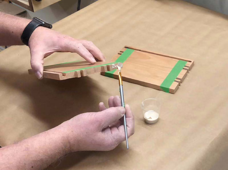
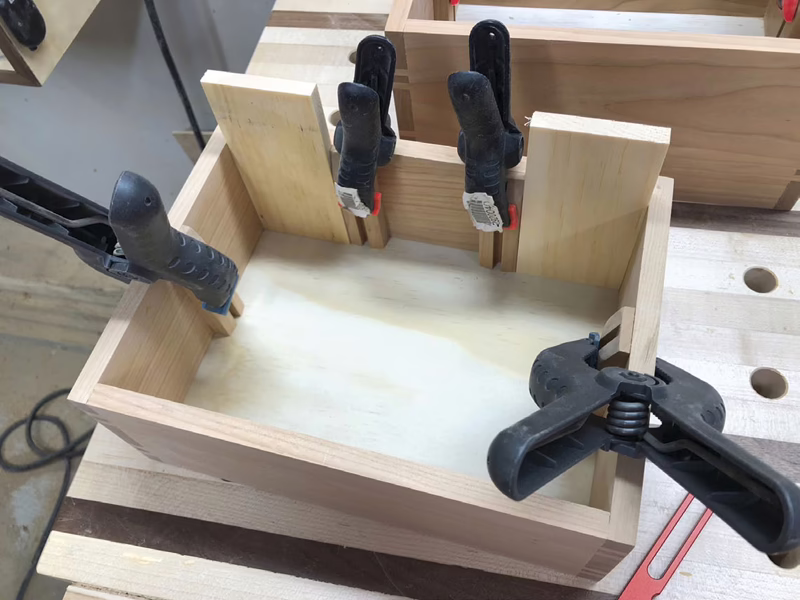
Whenever I’m assembling boxes, I always take a few moments to apply strips of painter’s tape to the inside edges of the joints. This small investment of time makes cleaning up any glue squeeze-out much easier after the joints are assembled. Next up is to spread glue in the joints and assemble the tray and base with the bottom panels in place. Check for square before setting the assemblies aside to dry. After the clamps are removed, sand the ends of the fingers flush at the corners.
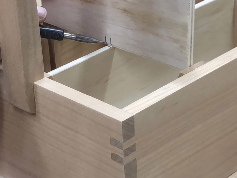
There is one more detail to take care of before moving onto the next stage. Cut some 1/2″ square cube-shaped feet to install on the underside of the tray. These feet are positioned in the corners to help align the tray with the base when the tray is stacked on top. Use a sanding block to slightly ease the exposed edges of the feet before gluing and clamping the blocks in place.
Can you handle this?
The next step is to make the carrying handle for the tray. The handle assembly is comprised of two uprights connected to a horizontal handle. The parts connect with each other with finger joints. The bottom ends of the supports are rabbeted to make the connection with the tray.
Begin by cutting the uprights and handle to size from 3/4″ thick material. Next, dust off your trusty box joint jig to prepare the joints that will connect the corners of the handle assembly. I used my box joint jig to machine these joints, but even a simple half-lap joint will also keep the handle-to-upright joints together for a long time.
The centre section of the handle is recessed to create a more comfortable grip. It’s easier to complete this recess before attaching the handle to the uprights. Lay out the shape of these indentations, then head over to the bandsaw to make the cuts. After sanding to remove the saw marks, install a 1/4″ round over bit in your router table to ease the edges.
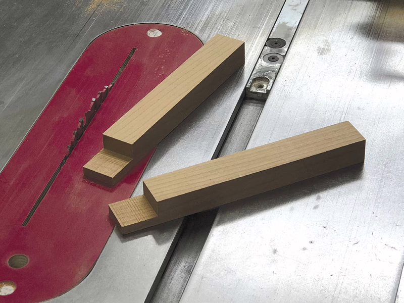
Mill a 1/2″ deep by 1″ long rabbet on the end of the uprights to anchor the parts to the tray. I was too lazy to switch over to a dado blade, so I just nibbled the material away by making multiple passes over a standard saw blade.
When all this work is complete, you’re ready to assemble the handle and uprights. Make sure the corners are square before setting the assembly aside to dry. It’s also a good idea to make sure the assembly will fit over the tray before it cures. You could even clamp the handle assembly to the tray while it’s drying, just to make sure it will fit.
After the glue has set, lay out the decorative 1/2″-radius curve on the top corners of the handle assembly and a 1/4″-radius curve on the bottom ends of the uprights. Make the cuts on the bandsaw, then sand the rough surfaces smooth. While you have the sandpaper in hand, you may as well use it to soften the remaining crisp edges on the handle assembly. When you’re done, install the handle assembly on the tray with glue and a spring clamp, securing each joint.
Divide and conquer
Prepare the partitions that divide the tray for tool storage and the base for seed packages. The partitions slide into grooved supports that are glued to the interior walls of the boxes. Start with the supports by ripping enough 1″ wide strips from 1/2″ thick material to yield all these parts. Next, mill a 1/4″ wide by 1/4″ deep groove down the centre of each blank. I did this at the table saw by making two passes with a standard 1/8″ kerf saw blade. I set the saw fence 3/8″ from the blade and completed the first pass. Then I rotated the blanks 180° before making the second pass. This technique will ensure the grooves end up being perfectly centred across the width of the material.
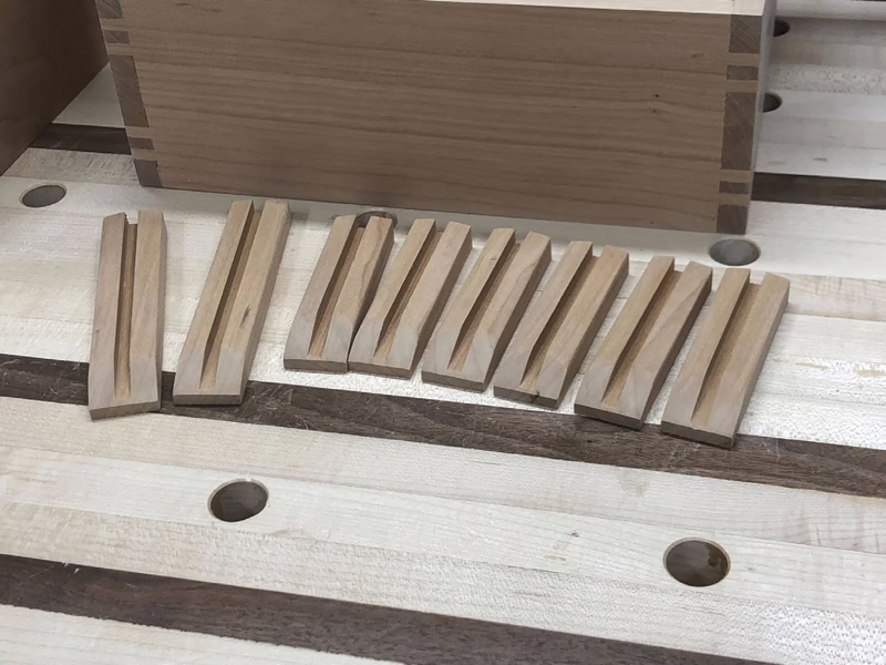
A decorative bevel is applied to the sides of the supports. I completed this detail by running the blanks on edge over a saw blade tilted 10°. Position your fence so the top of each bevel just kisses the edge of the slot. Run the blank on edge over the blade to complete the bevel on one side, then flip the workpiece end-for-end to do the same for the opposing edge. For safety, push sticks are a good idea to keep fingers well clear of the spinning blade when executing this procedure.
After profiling the sides of the blanks, cut the parts to final length and apply a matching bevel to the top end of each support. I used a stationary sander to form these tapers by eye, because it was much safer than trying to pass the parts on end over the table saw blade.
Now you’re ready to install the supports in the tray and base. Spread glue on the back and use scrap spacer blocks to prevent the parts from slipping around while you apply clamps.
Interior dividers
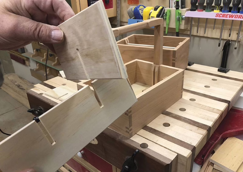
I made the interior dividers from 1/4″ plywood, but you can use solid wood if you prefer. Cut all these parts to size. The partitions for the tool tray are notched where the dividers intersect. For accuracy, it’s best to mark the locations of the notches with the dividers in position. To do this, slide the long centre divider into the support slots, then hold the shorter dividers in place on top to mark where the two parts meet. Take the dividers to the table saw and use the mitre gauge to cut slots halfway through the width of the material, using your pencil lines as your guide. This is another instance where a backer board is a good idea to prevent tear-out.
With this work done, slide the dividers into place and step back to see how you did. No glue is necessary here.
There’s a catch
You may have noticed that so far, no mechanical fasteners have been used to assemble this project. To keep that theme going, I decided to make an all-wood latching system to connect the top tray to the base. Each latch assembly consists of a thin latch arm with a slight hook on the top end and a spacer block on the bottom. One of these assemblies is secured on each end of the base. When the tray is placed on top of the base, the thin strips flex out of the way to allow the hooked ends to engage with catch blocks mounted on the ends of the tray. The hooked ends and catch blocks are bevelled to guide the parts into place when the tray is snapped into position on top. This is a clever design, if I do say so myself.
Start by ripping a thin 1/16″ thick strip from the face of a 1″ thick blank. This slice needs to be long enough to yield both latch arms. When completing this procedure, be sure to use a zero-clearance insert to prevent the material from slipping into the gap between the insert and the blade. It’s also essential that you position the fence so the thin strip falls free to the outside of the blade. Otherwise you run the risk of getting the material wedged between the blade and fence, which could lead to dangerous kickback. For this type of work in my shop, I built a thin strip ripping jig to get the job done safely. Once you have the thin slice of material in hand, cut the two latch arms to their finished length.
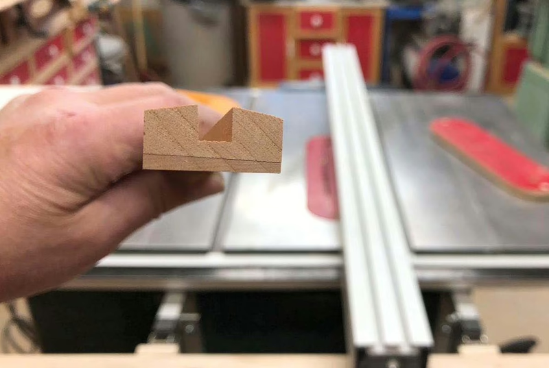
Next, turn your attention to the latch hooks, spacers and catch blocks. Start by preparing some 1/4″ material to make all these parts. It’s safer to bevel the edge of a wide blank before cutting out the tiny hooks and catch blocks to size. This is done by running the blank on edge over a saw blade tilted 15°. Use a zero-clearance insert and position the fence about 1/16″ from the blade to complete this procedure.
After bevelling the edge, return the blade to 90° and rip a 1″ wide strip for the hooks and catch blocks. Using the same setup, rip a second strip with square edges on both sides to make the spacer blocks. Now you can crosscut all these parts to length.
Apply a dab of glue to the back of the spacers and hooks, then use spring clamps to secure them to the ends of the latch arms. Make sure the bevel on the hooked end is oriented in the correct direction before leaving the assembly to dry. I learned this lesson the hard way. You can also apply glue to the back of the latch supports and install these parts centred on the ends of the tray.
After all this is dry, get out the glue bottle one more time to fasten the latch assemblies to the base. To get the positioning just right, start with the tray in place on top of the base. Now rest the hooks in position on the supports and clamp the spacers to the base using a single clamp stretching from one end to the other. Let the glue cure overnight before attempting to flex the latches clear of the supports to release the tray for the first time.
The finish line
Now that your handsome tote is fully assembled, go ahead and break out the sandpaper to prepare the project for the finish of your choice. I went with tung oil for my tote because I like how it enhances the cherry grain and it’s foolproof to apply.
After the finish dries, there’s nothing standing in the way of organizing all that seed-starting paraphernalia you managed to dig out of the backyard shed. Just be comforted by the fact that this is the last spring this annual scavenger hunt will be necessary.
Photos by Rick Campbell
Box Joints Are an Option
Campbell machined offset box joints with a dedicated jig for his garden tote, but other joints would also work.
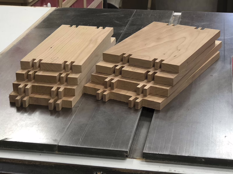
Nicely Cut
Here are the offset box jointed sides and ends, ready for the next step.
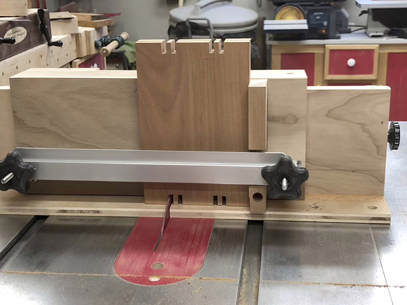
A Hole Lot Easier
Boring a hole into the start and end area of the bottom groove makes machining the groove a lot easier.
Keep It Clean
While Campbell applies glue to the finger joints and brings the sides and ends together, he uses masking tape along the inside of the joint to ensure a cleaner final result.
Cut the Grooves
With the holes bored, it’s time for Campbell to use his router table to machine the grooves. He does this with multiple passes and progressing depths as that’s safer and leaves a nicer groove.
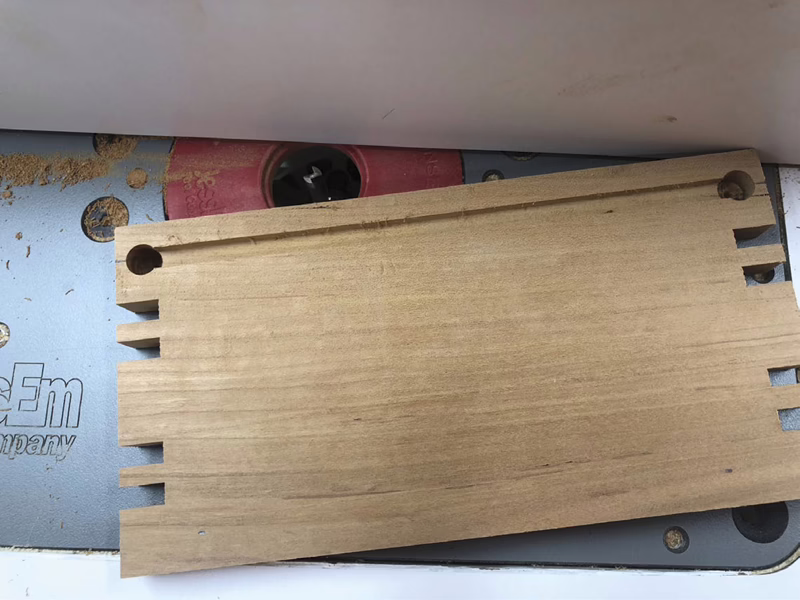
All Done
The finished grooves are now in each of the sides and end panels.
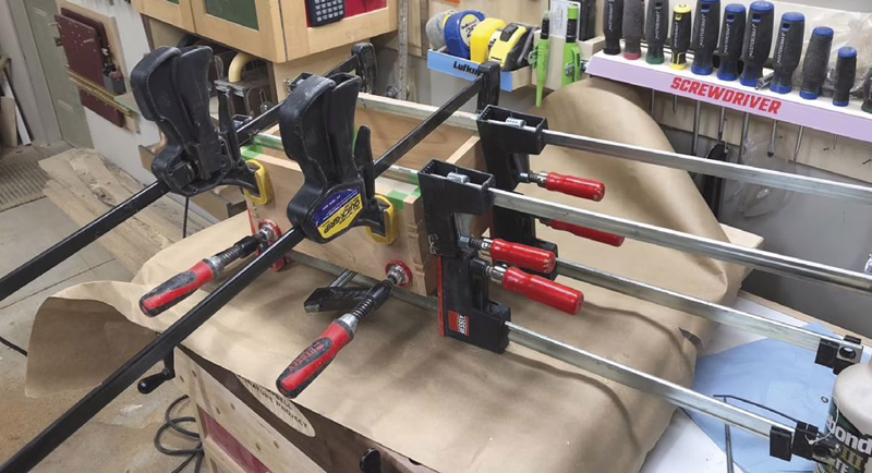
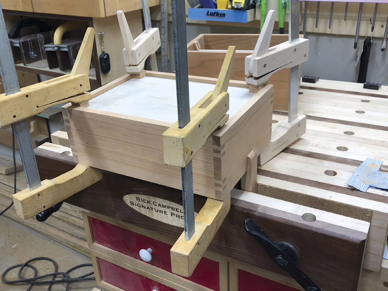
Let It Dry
With the sides and ends together, and the sub-assembly squared up, it’s time to let the glue dry.
Alignment Feet
Although these four feet are what the upper tray will stand on when it’s lifted off the base, the main purpose of these feet is to keep the upper tray centred over the base when they’re together.
More Fingers
Again, different joints could be used to fasten the handle to the uprights, but Campbell liked the look and strength of finger joints.
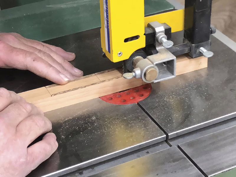
Better Grip
A notch is cut into the two sides of the handle to offer a better grip. Sand these two surfaces after they’re cut on the bandsaw.
Round It Over
A small round over bit installed in a router table will further ease the handle.
Centred Grooves
Campbell machined the first 1/8" groove slightly off-centre in the face of the grooved supports, then end-for-ended the workpiece and ran another groove. This left him with a 1/4" wide groove centred on the supports.
Nice Notches
Notches in the ends of the two uprights will allow the handle assembly to fit against the outer surfaces of the end panels and be glued in place.
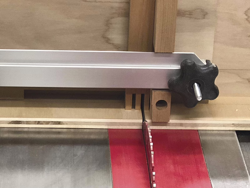
Bevel the Face
With the table saw blade set at an angle, Campbell machined a bevel into the two sides of the outer face of the grooved supports. This was mainly for the nice visual it created.
Ready for Glue
With the groove supports cut to length, then bevelled on their ends with a sander, they’re ready to be installed in the main box.
Scraps to the Rescue
Scraps cut to the correct width will help you keep the supports square and equidistant from the end panels while you glue them up.
Locate and Cut
With the main long divider in place, Campbell positions the short dividers above and marks where notches need to be cut into the short dividers.
Test the Fit
Once the notches have been cut you can assemble the dividers in the box. Glue isn’t needed to keep them in place.
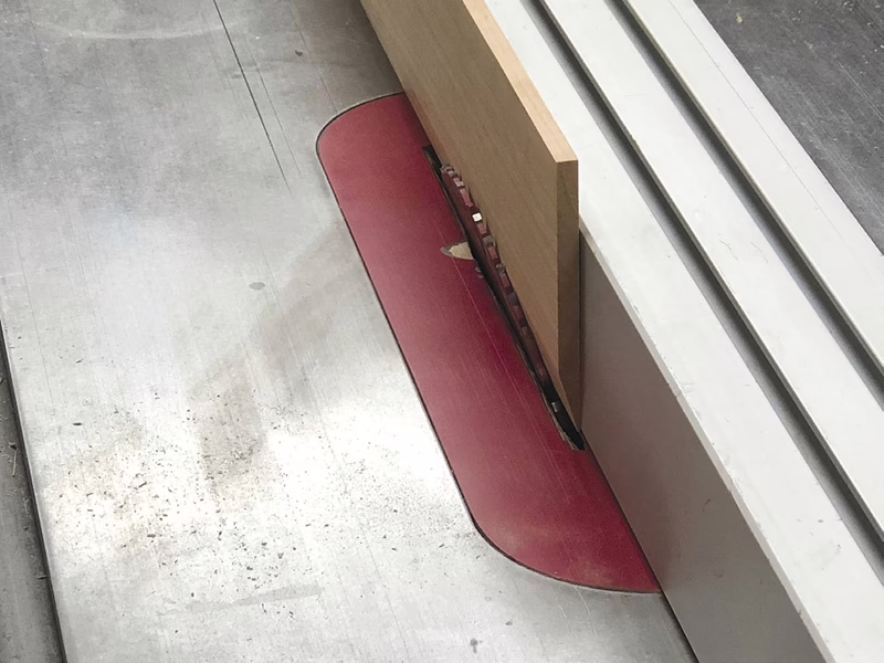
Bevelled Cleats
The latches that keep the tray fixed to the base work smoothly because of bevelled hooks and a flexible latch arm. Campbell rips the bevel into an oversized workpiece before ripping the bevelled edge off and cutting it to length to make each bevelled hook.
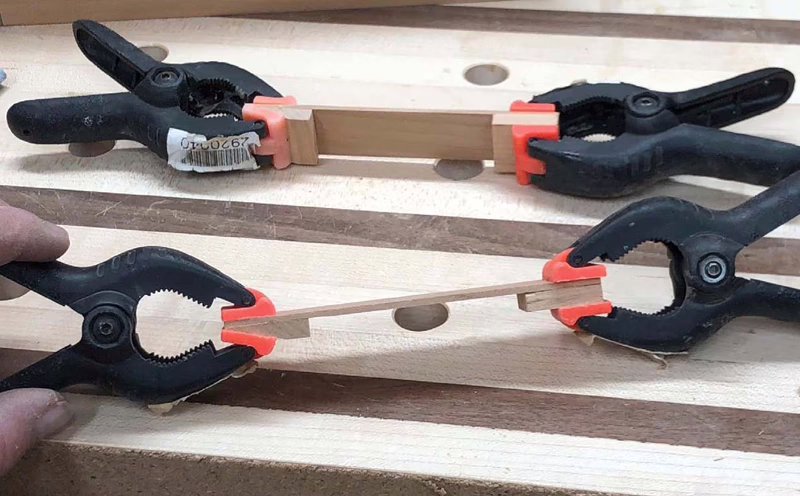
Light Pressure
Spring clamps will provide enough pressure to bring the bevelled hook and latch arm together.
Square It Up
Ensure the latch arm assembly is perpendicular to the base when you glue and clamp it in place.
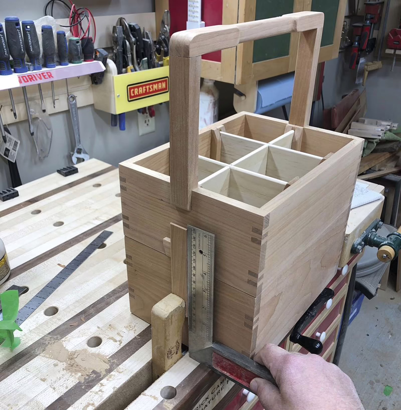
Illustration by Len Churchill


Do I need three hands to flex the two latches and lift the top tote at the same time?