PROJECT
Intarsia clock

Rick Campbell

Find more Home Decor projects
The entire project can be built in an afternoon from scrap wood found lying around the shop.
Most of the woodworking I do requires a great deal of planning, countless hours of shop time, and a substantial investment in materials. Usually the time spent on these major projects is enjoyable but sometimes I like to slow down the pace and turn my attention to something less demanding.
A perfect example of what I’m talking about is this easy to make intarsia wall clock.
I used South American padauk and rock maple for my clock but any combination of contrasting materials that look good together will be fine. You will also require a battery powered clock mechanism, a set of hands, a clock face and a pendulum. All of these parts are relatively inexpensive and are available at most specialty woodworking stores or by mail order from suppliers such as those advertised in this magazine. It is best to buy all your clock parts before you begin in case you need to adjust the project dimensions to fit.
Intarsia clock
Building the Base
From ¾” thick stock, cut out the two sides of the base with 45-degree mitres on the ends (Photo 1). Then rip a ¼” wide strip of contrasting material for the center spine. Double check the angles with a combination square – they need to be precise so everything will fit together properly.
Assemble the sides and spine with glue and clamps using a square to ensure the mitred tips align. In most cases, regular carpenter’s glue will do the job but, for mine, a two-part epoxy was necessary because of the unusual characteristics of the South American padauk I used.
The natural oils in padauk prevent traditional adhesives from curing properly – something to keep in mind whenever you use an exotic species of wood. Removing the surface oils with acetone before applying the adhesive will also improve the chances for a good bond.
While the glue dries you can begin working on the shell shaped end caps. The plans show that these are slightly wider and thicker than the main section of the base. Begin by cutting out a 4 ½” wide x 12” long blank from 1” thick material to yield both end pieces.
Continue by mitering all four corners of the blank at a 45 degree angle leaving a ¼” wide flat area in the middle of each end to match the center spine. Refer to the plan for complete details. Test fit the mitred ends in the “V” shaped openings formed on the main base and make any necessary adjustments. When you are satisfied, cut the base ends to length discarding the waste from the center of the blank.
Next, use a compass to layout a 2 ¼” radius curve on the square end of each end piece and then cut away the excess material at the bandsaw. When you are done, sand to remove the saw marks. Complete the base ends by rounding over the top edges using a table-mounted router and a bearing guided ¼” radius bit. While you’re at it, you may as well round over the outside edges of the main base section. Start in the middle and work your way to the ends in both directions to prevent breaking off the mitred corners.
Finish sand all the parts, then glue the caps to the base. A web clamp works best to hold it all together while the glue cures (Photo 3).
Time for the Clock
The clock mechanism is mounted inside a square housing that also serves as a spacer between the base and the clock face. Begin by cutting out the four sides of the housing, then mill ¼” deep x ½” wide rabbets on each end of the vertical members as shown in the plans (Photo 4). Make the rabbets using a straight bit installed in a table-mounted router, or nibble the material away at the table saw. Next, cut out an opening in the bottom piece to provide room for the pendulum to swing. The size and location will depend on the mechanism you have purchased.
Now you are ready to assemble the housing with glue and clamps (Photo 5).
When the glue has cured, round over the four corners of the box with a ¼” radius router bit as before.
Next, we tackle the circular frame that surrounds the clock face. Like the box for the clock mechanism, you may need to customize the frame dimensions to fit the dial you have purchased. I cut out my frame from a single wide board but you may find it necessary to edge join two or three narrow boards together to make yours.
Begin by using a compass or trammel to lay out the inside and outside of the circular frame on the square blank (Photo 6). Cut the outside of the frame at the band saw (Photo 7) and the inside using the scroll saw (Photo 8). When you are done, sand to the pencil lines using a stationery sander for the outside and a drum sander for the inside.
Return to the router table to round over the outside edges of the frame with the same ¼” radius bit used earlier, then switch to a bearing guided 45 degree beveling bit to chamfer the inside edge, on the top face only. Complete the frame by creating a ⅜” wide x ⅜” deep recess in the back to receive a Plexiglas dial cover using a bearing guided rabbeting bit.
I cut out the Plexiglas dial cover using the bandsaw after first laying out the circle with a compass (Photo 9). Make the insert 1/16” wider than necessary, then sand the edges to achieve a perfect fit.
The clock face is mounted on a piece of ⅛” hardboard cut ½” smaller than the diameter of the wooden dial frame. Drill a ⅛” diameter screw hole on each side of the hardboard circle to mount the board to the frame (Photo 10). Use a two-part epoxy to secure the backer board to the clock housing but be sure it is perfectly centered before applying the clamps and setting the assembly aside to dry.
The last piece you need to make is the pendulum weight. I turned mine on the lathe but if you prefer you can buy a commercial version from your clock supplier. If you make your own the plans provide the dimensions.
Putting it all Together
The clock housing is attached to the base using two 1 ½” #8 screws inserted from the back. No glue is used here so the housing can be removed to change the batteries. Be sure to pre-drill for the screws to prevent splitting the thin housing material. Counter-bore the heads so they are flush with the back. The position of the housing on the base isn’t critical just as long as it looks good to you.
Attach the dial to the backer board with double-sided tape and then drill a hole through the center to receive the clock shaft. Next, install the mechanism in the housing, then attach the hands and pendulum according to the manufacturer’s directions. Before attaching the frame to the dial board insert the Plexiglas cover in the recess but don’t glue it in place yet. With this done you can secure the housing to the base and verify that everything fits together properly. Now disassemble the clock and prepare to apply the finish.
Finishing Touches
Sand all the parts through 220-grit paper and apply a clear finish to highlight the contrasting materials you have selected.
If you used padauk as I did, avoid using any finish applied with a brush or a cloth because these may cause the dark orange colour to bleed into the surrounding lighter materials. For my clock I used several coats of spray lacquer sanding lightly with 600-grit paper between coats.
After the last coat is applied reassemble the clock, this time securing the Plexiglas cover in place with a few dabs of epoxy applied in the recess. You may have noticed that my clock has “Canadian Woodworking” printed on the face. I did this using my computer to print the customized dial on heavy glossy paper. This is a great way to personalize your clock with a meaningful message or maybe the image of a loved one or a favourite scene.
Cut a key slot in the back or add a picture hanger and you’re ready to display your handy work in a prominent place where it is certain to be admired for its beauty. Only you will know it was made using material rescued from the scrap bin.
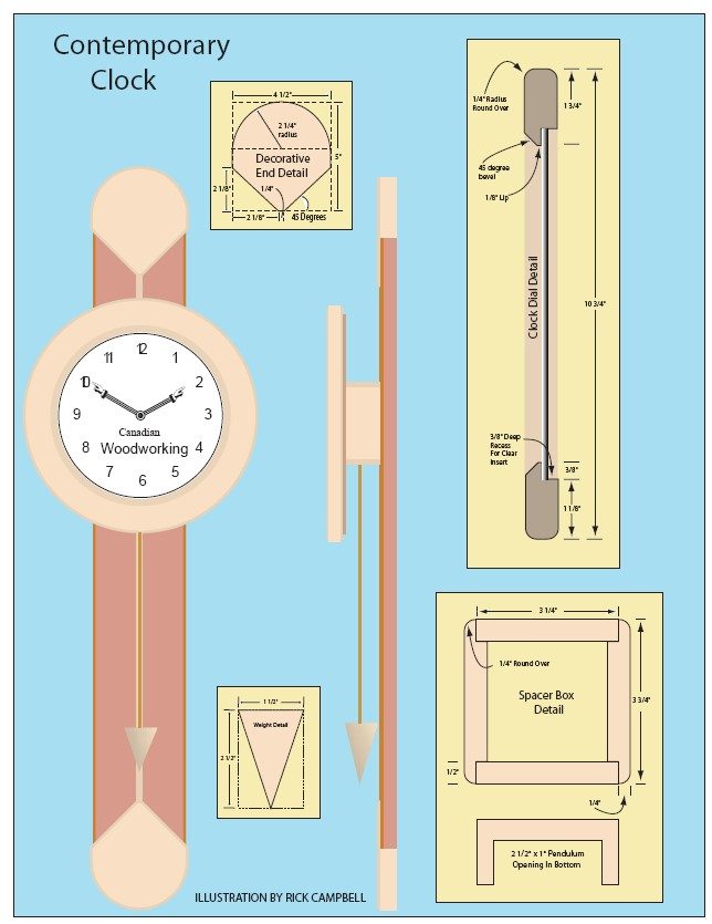
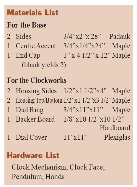
Illustration by Rick Campbell