Mortising jig
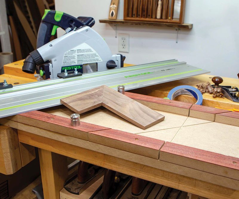
This versatile jig enables you to rout mortises for furniture construction and hardware installation.
Any jig used in the shop will enhance your woodworking, but when building a jig you must always come to a compromise somewhere between ‘simple to build’ and ‘versatile in use’. Make the jig too all-encompassing and it becomes overly complex to make and use. Make it too simple and you may find it of limited utility.
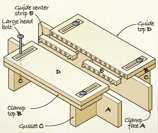
This jig consists of two parts: the top guide surface upon which the router sits and the clamping mechanism underneath. The top is fastened to the clamping mechanism using ¼” x 20 quick-connect hardware allowing it to be positioned anywhere on most common sized workpieces, and to be easily centered on the mortise using cross hair marks.
You’ll need to drill a lot of holes accurately to make this jig. I used the Dowelmax (dowelmax.com) however, you can use any dowelling jig that enables you to drill evenly spaced holes.
This jig is sized to fit a Triton MOF001KC router (tritonwoodworking.com) equipped with an ‘E’ (⅝” O.D.) guide bushing. You will need to adjust the measurements to suit the router and guide bushing you use.
The Clamping Mechanism
The top guide surface is centered on the layout marks on your stock using the cross hairs in the opening. The clamping mechanism is then snugged up against the workpiece and locked in place with the large head bolts (leevalley.com) and a pair of clamps secure the jig to the workpiece.
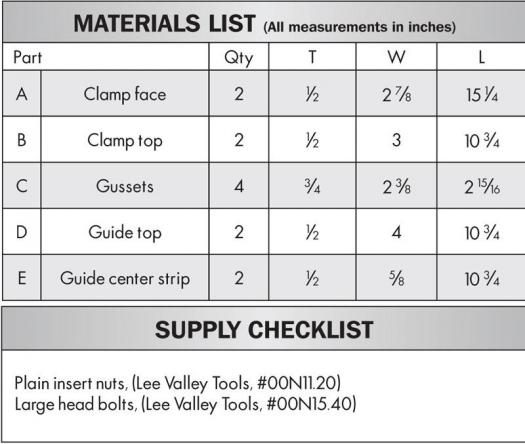
• Cut the clamp face pieces (A) to size. These will be in contact with the workpiece when the jig is in use.
• Cut the clamp top pieces (B) to size; these will be in contact with the underside of the guide top (D). Drill two 13/32″ holes in each piece (as shown).
• Drill dowel holes along one edge of each top piece (B). Drill a corresponding set of dowel holes centered on the upper edge of the clamp face pieces (A). Using dowels and glue instead of screws makes it impossible to damage a bit should something happen through operator error that has the bit coming in contact with the edges of the clamp face.
• Cut the four gussets (C) to size; these strengthen the connection between pieces A and B and house the insert nuts.
• Drill a 2″ deep hole in the top of the gussets, 1-3/4″ in from the inside edge and install a plain insert nut in the bottom of each hole.
• Glue and assemble the top and face pieces. Use clamps to ensure a tight joint.
• Apply glue to the top edge and inside edges of the gussets (C), place 1/2″ spacers over the top pieces (B), insert the large head bolts through the spacer and the top piece and into the gussets (C). Tighten the bolts, and then drill two countersunk pilot holes and drive two steel screws through each top piece and face piece into the gussets. Apply clamps and let the glue set. Once the glue is dry, remove the steel screws and replace with brass screws.
The Top Guide Surface
The top guide surface is what supports and guides the router through the cut. The configuration of the top makes it possible to cut any size mortise by simply making up additional center pieces (E). Label each pair of center pieces to indicate the size of the mortise they are used for.
• Cut the two guide top pieces (D) to size and drill a series of dowel holes along one long edge of each piece. Fit the two pieces together with a couple of dowels and use a knife to mark the center along the length of the joint. Separate the pieces and use a scroll saw to make a shallow 1/8″ cut at the knife mark; these will be the cross hair marks used to center the jig on the mortise layout lines, lengthwise.
• Install a 5/16″ spiral bit in the router table, and using a fence and end stops, rout the two mortises required for each large head bolt.
• Prepare the solid wood strip for the guide center strips (E) and drill corresponding dowel holes along their length. My center strip was 5/8″ wide to accommodate the ⅝” bushing on my router.
• Fit the solid center strip to the side pieces and use the cross hair cuts to center the cut lines to create a 1-9/16″ opening. Cut the waste piece out of the center using a mitre saw or a cross cut sled on the table saw.
• Measure the width of the center strips and use a marking gauge to mark the exact center of each piece at the opening. Make a 1/8” deep cut with the scroll saw for the cross hairs to form the second axis.
• To assemble the jig, use dowels without glue to connect the four top pieces. If you want to cut mortises of a different size, simply make a new set of center pieces (E). Using a large head bolt, fasten the top guide assembly to the two clamp mechanism pieces.
Using the Jig
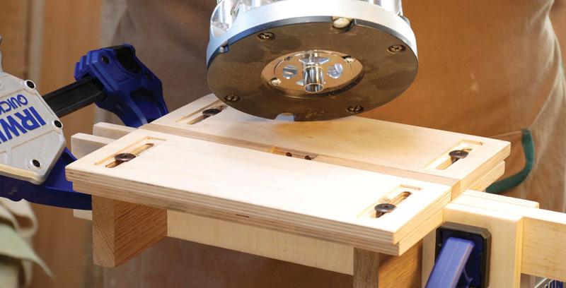
Prior to using the jig, lay out the mortises on your stock; mark the center of the mortise on both axes. Loosely fasten the clamp mechanism to the underside of the router guide and place the jig on the stock and center the jig on these lines using the cross hair marks. Snug the clamp mechanism up to the material and then use some Irwin Quick-Grip clamps to secure the jig to the workpiece. Tweak the final placement of the top on the layout lines and then tighten the large head bolts. With the jig now secure you can rout the mortise.
For production work such as when joining legs and an apron on a table, mark one side of the clamping mechanism and leave that side securely fastened in place. Use this side as a common reference face and adjust the other side of the clamp for any variation in material thickness. The top guide surface can also be clamped directly to a flat surface when working in the center of a larger panel.
Mortise and tenon joinery is one of the most commonly used woodworking techniques, and this jig will help you make perfect mortises every time.

Carl Duguay - carlduguay@gmail.com
Carl is a Victoria-based furniture maker and the senior editor at Canadian Woodworking & Home Improvement.